


1. Electrode Preparation and Testing
Various methods, including magnetron sputtering, thermal evaporation, and chemical synthesis, are employed to fabricate flexible and stretchable electrodes. These electrodes come in different forms, such as thin film electrodes, fiber electrodes, and gel electrodes. Upon completing electrode fabrication, they undergo rigorous testing to assess their properties, including stretchability, channel conductivity, interference, and waterproofing. This process ensures that the implanted electrodes exhibit excellent electrical conductivity, stretchability, waterproofing, and a high degree of reliability and stability.
2. Preparation and Testing of Soft-Hard Interfaces and Skull Interfaces
The flexible electrode interface utilizes anisotropic conductive film to connect to one end of a custom PCB board. The other end of the PCB board is where stainless steel wires are soldered for each channel. The interface is secured using heat shrink tubing or sealing film, and 734 adhesive is used to further seal the soft-hard interface. Upon completion, the soft-hard interface is tested for its sealing properties in a continuous immersion environment, and the electrical conductivity of the stainless steel wires passing through the soft-hard interface to the rear electrode monitoring points is checked. The channels of the skull interfaces are soldered to the other end of these stainless steel wires. To ensure the standardization of implantation experiments and the reliability of data collection, the main testing contents in this section include (mark the checkboxes inside the squares after inspection):
Conductivity of the Device
□ Secure connection between the skull interface and the electrode contact points (theoretical range: 15-120Ω).
□ No channel cross-talk observed at the female plug of the skull interface.
Conductivity of the PCB Board and Stainless Steel Wire Conductors
□ Good connectivity of each channel after soldering (theoretical range: 10-100Ω).
□ No cross-talk between channels after soldering.
Conductivity of Stainless Steel Wire Conductors and the Skull Interface
□ Prior to soldering, the pins on the skull interface itself should exhibit normal resistance (theoretical range: 0-10Ω) and should not cross-connect.
□ After soldering, there is good connectivity between the PCB and the corresponding skull interface channels (theoretical range: 10-80Ω).
□ No channel cross-talk is observed at the female plug of the skull interface.
3. Comprehensive Testing of Electrode with Skull Interface
The main testing procedures are as follows:
Assessing Device Conductivity
□ Measure the direct current resistance between each channel and the corresponding electrode using the skull interface.
Checking for Short Circuits Between Device Channels
□ Measure the direct current resistance between different channels.
Channel and Inter-Channel Impedance
Immerse the electrode monitoring points in a PBS solution, and assess the alternating current impedance between channels and inter-channel impedance from the skull interface.
□ Assess the alternating current impedance of each channel.
□ Evaluate the alternating current impedance between channels.
Waterproof Performance of the Soft-Hard Interface
Place the device in a constant-temperature (60°C) water bath shaker for one week. During this period, periodically dry the electrode monitoring points and assess the direct current resistance of each channel.
□ Measure the direct current resistance between channels and inter-channel resistance at the skull interface.
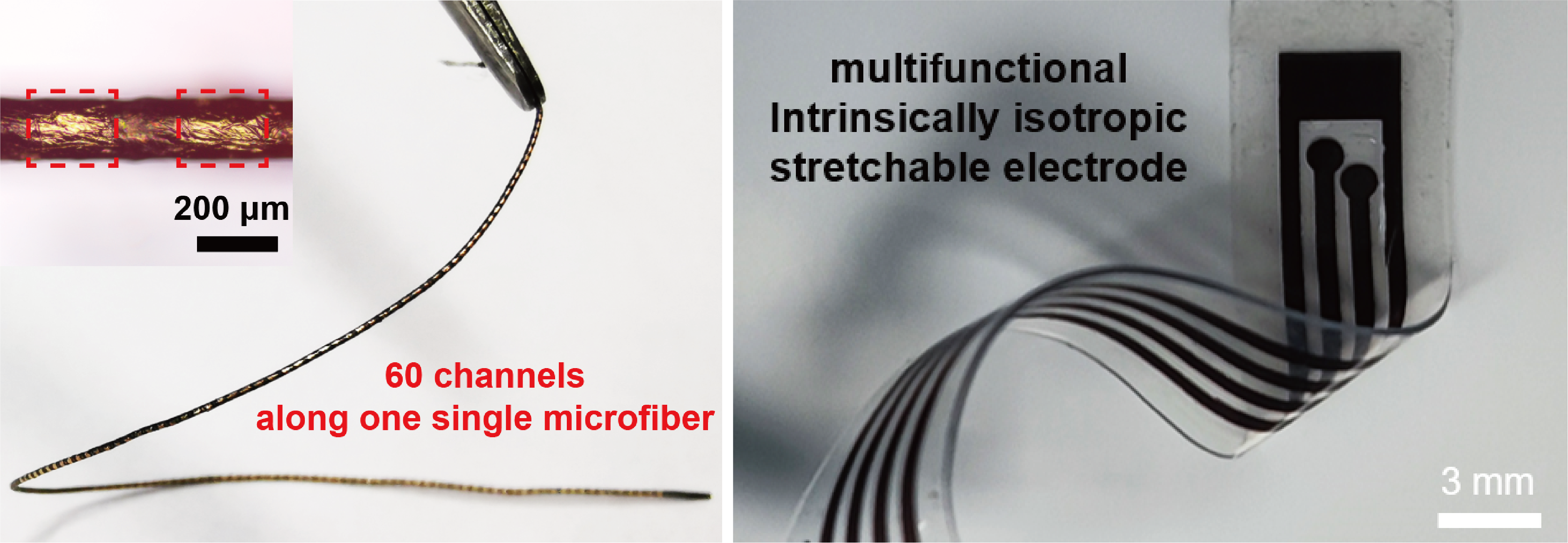
Pictures of different kinds of electrodes: Along-one-single-fiber Multi-function Stretchable Electrode Array; Multifunctional Intrinsically Isotropic Stretchable Electrode.