


Following the implantation of electrodes into rats, factors such as the rats' individual health, immune response, external environment, and more may lead to the gradual demise or euthanasia of the rats several months or years later. This may be due to illness, natural lifespan, ethical considerations, or data collection requirements. Upon the passing of the rats, a standardized dissection procedure becomes essential for the analysis of a significant volume of implanted data and for the study of the implanted electrodes. Therefore, we have developed a specialized dissection protocol tailored for flexible electrodes through ongoing experimentation. The detailed steps and testing procedures are as follows (mark the checkboxes inside the squares after inspection):
Anatomy Procedure Template for Long-term Implantation of Electrodes in Rats
(Applicable to implants with the electrode device composed of "electrode + soft/hard interface + stainless steel wire + cranial connector")
Rat ID:
Implantation Date:
Dissection Date:
Rat Weight:
Overview of Rat's Basic Information:
Implantation of Electrodes Morphology
(with illustrated explanation, including channel and other relevant details):
Skull Interface
(with illustrated explanation, and indication of the correspondence between its channel and electrode channels):
Implantation Plan
(with illustrated explanation, indicating the electrode implantation site and the path of the device channels):
Preparations Before Rat Dissection (Mainly for the final data collection while the rat is still alive):
1. Conduct the final data collection according to the established data acquisition protocol for this rat.
□Collect data according to the routine protocol.
□Analyze data for any unusual observations, and make preliminary assessments of the causes if anomalies are detected.
2. Perform X-ray imaging on the anesthetized rat, with a primary focus on the electrode site and the soft/hard interface site. Compare the appearance of these two areas with how they looked right after implantation. Estimate the condition of the electrode inside the rat at this time.
□Capture images of the implantation site □Capture images of the soft/hard interface
□Compare X-rays with those taken one week post-implantation, and provide an estimation of the electrode's condition inside the rat (describe any observations, such as displacement or other anomalies).
3. While the rat is under anesthesia, physically connect the leads to the cranial connector fixed on the rat's skull to measure the impedance and DC resistance of individual electrode channels and the inter-channel impedance when the electrodes are inside the rat.
□Measure the AC impedance of each channel (channel to ground)
□Measure the AC impedance between channels
□Measure the DC resistance of each channel (theoretically non-conductive)
□Measure the DC resistance between channels (theoretically non-conductive)
Dissection Steps: (The following steps primarily focus on the performance of the device and the foreign body response, and do not include details related to rat anesthesia and euthanasia. It is assumed that the rat has already been anesthetized before these steps begin, and euthanasia is performed after the specimen collection is completed.)
Before dissection, we need to conduct electrical performance testing on the complete implanted device in the rat. The step-by-step dissection and analysis allow us to identify any unstable components within the electrode device. This information serves as a basis for improving the electrode device and extending the duration of monitoring after implantation in the future.
1. Macroscopically, begin with a visual examination of the electrode device's physical connections, the presence of any displacement at the implantation site, and the status of tissue encapsulation. The specific procedure is as follows:
1.1 The main path of the electrode device inside the rat is "cranial-back-electrode monitoring site." Therefore, incise the rat's back skin to locate the electrode device.
1.2 Cut along the path of the electrode device, incising the rat's skin, and observe the condition of the electrode device.
1.3 Take photographs or record video, with a focus on the physical connections of the entire device, electrode condition, tissue condition, and any signs of displacement in the implant.
□{Take photos} Observe the device's connection status (whether the connections are intact or if there are any breakages).
□{Take photos} Observe the condition of the electrode implantation site (if there is any displacement).
□{Take photos} Observe the morphology of the electrode inside the rat (differences compared to the time of implantation).
□{Take photos} Examine the tissue encapsulation of the implanted electrodes.
2. Analyze the stability of the components of the electrode device step by step. Begin by cutting and identifying the stainless steel wire leads between the cranial connector and the soft/hard interface. The specific steps are as follows:
2.1 Using micro forceps, separate the tightly encased tissue from the stainless steel wire leads until a segment of the stainless steel wire is fully exposed. Remove a portion of the insulation layer from the stainless steel wire leads using micro forceps.
2.2 Determine the specific channel number of a wire by measuring the DC resistance between the section where the insulation layer has been removed from the stainless steel wire and the channels in the cranial connector. The corresponding channel resistance should ideally fall within the range of 30-100Ω, with very few exceptions floating into the kΩ range.
2.3 Mark the channel numbers on both ends of all stainless steel wire leads where the insulation layer has been removed. Each stainless steel wire lead should be labeled twice for clear identification.
2.4 Cut the stainless steel wire leads at the point where the insulation layer has been removed. Designate the cut point on the wire leading to the cranial connector as "A," and the cut point on the wire leading to the soft/hard interface as "B."
□Check and test each marked channel individually.
□Record the DC resistance for each stainless steel wire channel to its corresponding cranial connector common wire.
3. To test the seal integrity of the cranial connector, measure the electrical data between the cranial connector and the midsection of stainless steel wire leads.
Suspend the stainless steel wire lead at point A, and at the cranial connector, test the AC impedance between each channel (channel to ground) and between channels to determine if the cranial connector is intact (higher AC impedance indicates a well-sealed cranial connector).
□Measure the AC impedance between each channel (channel to ground).
□Measure the AC impedance between channels.
4. To determine the performance of the "electrode + soft/hard interface + stainless steel wire" portion, you can perform the following steps.
Measure the AC impedance and DC resistance between each channel (channel to ground) and between channels using the stainless steel wire lead B break point. When the electrode is a single channel, insert the RF to measure the AC impedance and DC resistance between channels.
□Measure the AC impedance between each channel (channel to ground).
□Measure the AC impedance between channels.
□Measure the DC resistance of each channel (theoretical value should be MΩ).
□Measure the DC resistance between channels (theoretical value should be MΩ).
5. Cut the electrode in the middle, label the point near the soft/hard interface as "Electrode C Breakpoint," and the point near the conductive detection as "Breakpoint D." Suspend the Electrode C Breakpoint to ensure that its cross-sectional conducting part doesn't touch the rat, and measure the AC impedance and DC resistance between each channel (channel to ground) and between channels at the stainless steel wire lead B breakpoint.
□Measure the AC impedance between each channel (channel to ground).
□Measure the AC impedance between channels.
6. Observe the soft/hard interface after tissue removal.
Detach the "stainless steel wire lead B breakpoint - soft/hard interface - electrode C breakpoint" from inside the rat, peel away the tightly enveloping tissue at the soft/hard interface, and observe the differences in the external appearance of the soft/hard interface compared to before implantation.
□{Take photos} {With the naked eye}, observe the condition of the soft/hard interface.
□{Take photos} {Under a surgical microscope}, observe the condition of the soft/hard interface.
7. Place the "stainless steel wire lead B breakpoint - soft/hard interface - electrode C breakpoint" in a PBS (Phosphate-Buffered Saline) solution and measure the DC resistance between channels at the stainless steel wire lead B breakpoint.
□Measure the DC resistance between channels.
8. Cut open the soft/hard interface and sequentially separate the electrode, PCB board, and stainless steel wire leads, inspecting the encapsulation compared to the condition before implantation.
9. Use a surgical blade to obtain a section of muscle tissue containing the implanted electrode, and fix the tissue for subsequent staining and slicing.
10. Take another section containing the exposed conducting part of the electrode and use light microscopy and electron microscopy to capture the surface morphology of the electrode.
□Electrode Surface Morphology - Light Microscopy
□Electrode Surface Morphology - Electron Microscopy
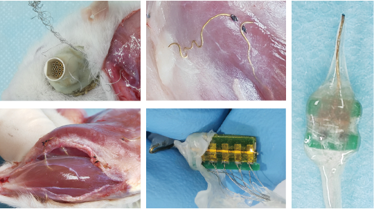
Typical cases during dissection: stainless steel wires scratched out by the rat at the skull interface, breakage of fiber electrodes implanted in muscles, intact distribution of fiber electrodes within two muscle blocks, and well-performing soft-hard interfaces.